Showing posts with label Design A Drawing Machine. Show all posts

Friday, March 14, 2014

Design a Drawing Machine

After many many iterations here is the final piece "Design a Drawing Machine" 


I realized having 3 interchangeable gears made it more interactive and interesting to tinker with, but with so many degrees of freedom it gave kids too much free reign to stack gear towers and go wild. I think my previous prototype would be good as a game kit sold in stores, but for an exhibit, something that is more simple to interact with but still interactive and less complex was my goal:


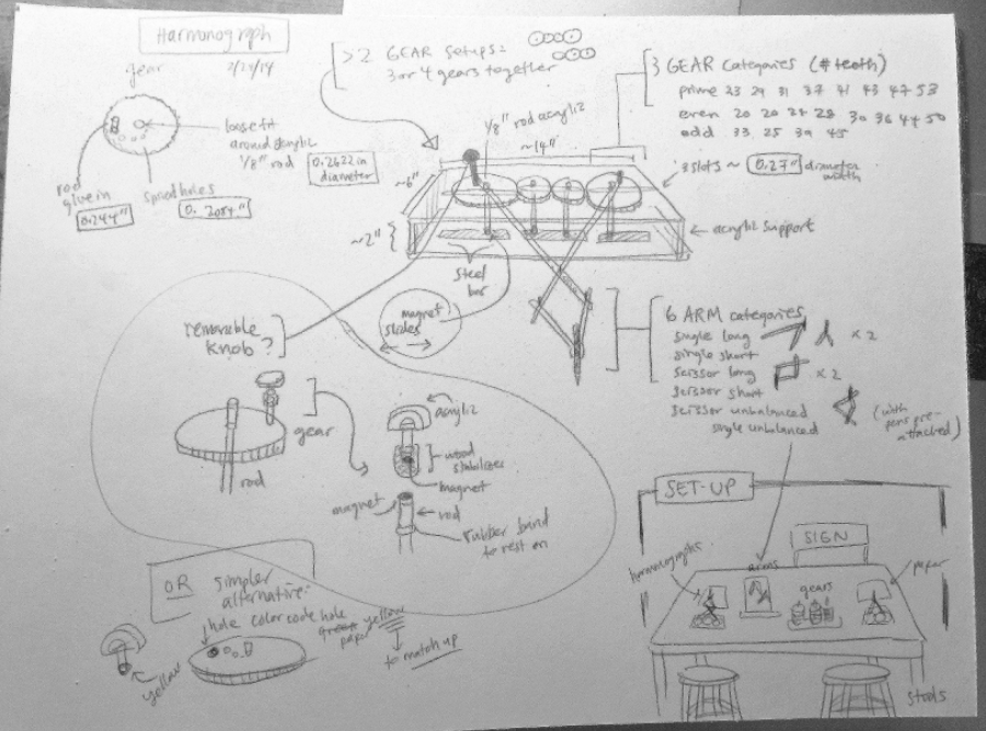
Slippage prevented with discrete holes:


Affordances: a knob to crank


Label:


Photos from the Exploratorium floor:


Tuesday, March 4, 2014

Design a Drawing Machine

I named my exhibit prototype "Design a Drawing Machine" because I wanted the title to evoke the fact that the user is actively engaged in building the machine by selecting which gears and types of arms.


Challenges of Prototype Creation:

I made a lot of changes from my last prototype to this first iteration on the exhibit floor. One of my primary focuses was on enhancing user experience: color coding gears by even/odd/prime, sliding magnets, a way to color code and match up the handle/knob to the dowel, and more (thinking of affordances from the Exploratorium article we read.) Changes I made included:

  • Neodymium magnets and rubber band tension system: I designed an easy way to add and remove different sized gears by sliding the center dowels. The original challenge was that weding in the wooden dowels took too much effort and precision and was not at all intuitive or easy for the user. (This magnet band set-up took a lot of tricky tinkering and testing to set up, and still, I found out through testing on Friday that this needs to be improved)
  • Better construction of the harmonogram base, including a handle for the left hand to grip and exert downward pressure with (U-bolt)
  • Additional progress: color-coding and labeling gears based on # of teeth: blue is even, gray is odd, orange is prime.
  • Constructing 5 different arm types (scissor, single, uneven lengths, long, short)
  • A stand to carry the removable and exchangeable parts

A problem I still had after I finished the prototype was slippage: because the rubber band magnet system only exerts the right pressure when certain gear sizes are paired up, often the gears would slip over each other, or slip away so that contact is lost. While I solved the problem of easily switching out gears by creating a new mechanism for doing so, I created a new problem in the process, which was gear slippage. I tried to mitigate this issue by adding a sign and label that suggested gear ratios / gear sizes for the exhibit user to test out. These gear pairings were selected so that it would stretch the rubber bands just the right amount to hold everything tightly in place without creating too much slippage pressure. Of course, I later learned that no one reads signs.

Experience on the Exploratorium floor:


I had a very illuminating experience on the Exploratorium floor. My most pleasant surprise was the kids were actively engaged in the harmonograms and spent a few minutes with the exhibit; there were many people who spent over 5 minutes tinkering with the same drawing machine. Knowing that most people spend less than a minute at a given exhibit, I was pleasantly surprised. I think the drawing aspect of the exhibit makes it hands-on and engaging for the kids. 
I was also happy with the parental interaction with kids. Often times the parents did a great job of encouraging the child to use the machine correctly "Look, there's a 'turn this' label on this handle. You should turn here." But several times the parents themselves also didn't quite get the interaction correct in terms of which hand goes where and how to set up the machine. I think this was my fault as the designer not putting sufficient cues or diagrams to help. 

I was also very pleasantly surprised by the collaboration between kids. I heard one kid tell the other, "If you have a bigger gear it helps" or "Put that gear here." Even though these kids were elementary school students, they were still thinking critically and helping each other out.

"Pile on all the things!" I noted that none of the kids under middle school level set-up the machine correctly; I realized kids have a tendency to want to pile on as many things as possible onto a machine, when given spare parts to choose from, in this case, gears and arms. Of course, these machines didn't draw the curves, let alone budge at all. However, I noticed kids were happy just to have drawn some scribbles on paper. It seems kids like 2 things: making marks (with pen, pencil) and chaos.

Other problems I noted:
  • Gear slippage when too much pressure was put in turning the gears. Usually kids would react to this gear slippage by cranking it even harder. This, of course, does not help.
  • The other visitors were more calm and steady, but there was still gear slippage from time to time. More often than not they were still applying too much pressure.
  • Girls were more patient.
  • Older visitors are more patient. When one of the kids patiently set up the machine and made it work, I deliberately asked for his age: 8th grade.
  • People didn't know how to hold the machine. Many people tried turning it with both hands when in fact 1 hand was easier. Some would hold no handles. I should make the affordances better for this aka make 1 handle look like a knob and the other one shorter
  • People didn't set up the arms correctly. They would set the arms in the enter dowel, which of course doesn't move the arm at all. I should have a diagram to help guide users.
  • No one reads signs
  • No one reads labels. Even the labels that were directly on the machines were ignored such as "Turn this" or "hold here." Sometimes the parents would notice that let the kid know, but more often that not they were completely overlooked.
  • Because of the abundance of gears and arms to switch out (many degrees of freedom) I noticed that the users were spending a lot of time playing with gears, and not much time actually cranking the machine to produce the end resulting curve. In my next iteration I might want to have less variability and less chaos.
  • A lot of users benefited from seeing someone else do it correctly first so at several points during the afternoon I would pretend to use one of the machines as if another Exploratorium visitor, and since there were 2 harmonograms, I hoped others would step in and try to mimic my motions
Many many many scribbles and the result of a kid putting 3 arms on 1 harmonogram


I think a lot of my experiences reflected what Alice said about how "people are not as intelligent as you think." For instance, they would continue to turn the gear even after the gears had slipped and it was clear the turning had no effect. But perhaps I should give them credit and say instead, "people are not me." As the creator, I know where to put the arms, which knobs to hold, and exactly what pressure I should crank the gears so that it doesn't cause them to slip.

Visitors' interactions with classmates' exhibits:


What I noticed for most of the exhibits is that kids like swarming. They swarm around an exhibit 5-7 kids at a time, which results in interesting side-effects, such as in Winnie's case, kids sometimes blocking the light source. Kids also love using exhibits in an unintended, often dangerous way, as I noticed when they picked up the lasers from Dan's exhibit and started pointing them at each other's faces. 

Changes and improvements based on my experience on the floor:

My plan for the final iteration is twofold:

  • First, I want to redesign the machine so that instead of slots and sliding magnets, I have discrete holes that securely hold the rod in place. Instead of 3 moveable gears, I will have the center gear set in place, since that one is just to move the other 2 gears in a ratio and its own size has no significance. This way, with 1 gear anchored, it is easy to create discrete, tight fitting holes for the other gear sizes on either end. I hope this will solve the problem of gear slippage and simply make it more intuitive to use.
  • Next, I want to improve affordances by making handles were necessary and color coordinating where each item goes (ie. match the yellow-marked rod with the yellow hole.) I will also have a large diagram of what the final set-up looks like, and what a user looks like when cranking the machine (like the "magic want" diagram)

The beginning
The aftermath

Friday, February 21, 2014

Sketches: Hand-Cranked Harmonograph

Isometric View
Top and Side Views
Close-up details of actual harmonographs
Additional sketches:


Tuesday, February 18, 2014

Prototypes Take 2 (Anamorphic Images and Hand-cranked Harmonographs)

The task for the week was to improve upon two of our prototypes: I decided to iterate upon Anamorphic Images "Why the Long Face?" and Hand-Cranked Harmonographs:


Anamorphic Images "Why the Long Face?": As I mentioned in my 1st prototype blog,  when the class interacted with the first prototype many people seemed to want to interact with the mirrors and images so I decided to focus on making the prototype more interactive. I used a combination of printed templates and acrylic with whiteboard markers so that users could draw on the acrylic to try to create hand-drawn anamorphic images, then easily erase it so the next person can try. I had my prototype in a progression:


  • Station 1: “Why the long face?” Can you guess who’s who? Now look at the reflection in the cylinder: now can you tell who’s who? 
  • Station 2: “Give it a try!” Try drawing an image freehand without guides so that the reflection in the mirror looks normal. Is the reflection what you expected? What surprises you? 
  • Station 3: “Guides” Now give it a try with some guidance: draw an image on the square grid, then transferring the image to the polar coordinates square by square. 
  • Station 4: “The Mighty Morph” Draw a normal picture on the screen and see the computer do the magic! How do your 3 images compare?

The idea was that through this flow, visitors can think critically and explore the concept of warping and anamorphic images, and try their hand at making these images themselves through free-form or more guided processes (free-draw vs guidelines vs the computer) which sheds light on just how easy or difficult it may be to create these drawings.

Station 4 was inspired by a students comment a few weeks ago about my prototype 1, where she mentioned it might be cool if instead of drawing a warped image on guidelines, we could draw a normal images on stretchy material, warp it, and then have it display correctly in the mirrored cylinder. To achieve this I decided to use a computer program to leverage the fact that I'm a CS major. Creating the program actually took quite some time because it turns out I didn't have many many things installed (updated verison of XCode, XCode console tools, Tkinter, ImageDraw, etc...) and installing things leads you down a rabbit hole that takes hours before you manage to dig yourself out again... After that whole ordeal, I was able to write a program that popped up a drawing console where the user could draw an image, click "Morph It!" and it automatically creates the warped image, perfect for reflection in the mirrored cylinder. You can write a sh script that converts from rect to polar coordinates to achieve this effect. Tools used: Python + Tktiner GUI Package for the drawing window. Then a rect to polar shell script for the warping of the image. In a final exhibit I'd have the computer be a tablet (so users don't have to draw with a touchpad) and the entire screen would be projected on the ground so that users can interact in a larger space rather than just on a small digital screen.


Student feedback was positive and they thought that both prototypes (this one and the one below) would make for great potential exhibits. Many people mentioned that their favorite part about the anamorphic images exhibit was when they could actually draw on the acrylic and see their images reflected in the mirror. It seems that like that part was the more engaging and tactile point of the process, whereas the mirrors with pre-printed images was a bit too passive, and the computer program was perhaps a bit too passive as well. 

Hand-Cranked Harmonographs: The second prototype I wanted to iterate upon was the harmonograph. I tried to make a motorized version to complement the hand-cranked version. However, it turns out that the slow moving motor was a bit too slow, and the arms were a bit loose in relation to the screws, and the end result was that the prototype was too wobbly to create a smooth image with a motor spinning that a low speed. Thus if I were to improve upon this I would make tighter fitting parts and find a faster motor. However, there seems to be a consensus that the hand-cranked prototype is preferred over the motorized version, since the hand-cranking gives it more interaction. And I agree when I crank it myself I can feel the pressure and forces changing at different points in the curve drawing and it's interesting to physically feel the differences not just see the pattern. I ultimately chose the harmonograph as the prototype I'm going to work on for the final exhibit, because I feel that it gives me more opportunity to build things in the PRL and work with the laser cutter and gears, something that is entirely novel and fascinating for me as a CS major who hasn't had much practice building physical things. I also see a lot of opportunity in enhancing user interaction, and there are a lot of different ways to create gear harmonographs out there that I'd like to tinker with and enhance for user interaction and exploration!


Hand-cranked gear harmonograph in the front and a new motorized version in the back

Sebastian and John listening attentively

Thursday, February 13, 2014

Mechanics I and II: Hand-cranked Harmonograph and Spirograph


Prototype I: Hand-Cranked Harmonograph

Project in a Nutshell: I created a hand-cranked harmonograph with a set of exchangable gears with different teeth #s so users can create unique patterns and discover the effects of different gear ratios on the pattern outcome. In general, mechanical harmonographs use either pendulums or cranks for oscillators. The movement of a horizontal crank when viewed from the side is the same as that of a pendulum when viewed from the bottom. Both are examples of harmonic motion, and they create different types of curves, often resembling Lissajous curves, which are graphs of a system of parametric equations which describe complex harmonic motion. [Video to be added soon -- at the time I couldn't manage to hold my iPhone and crank the harmonograph both at once]


Concept and Evolution: I originally wanted to create a harmonograph with pendulums, similar to one of Britt's mechanical prototypes. Thus I researched ways to build harmonographs and found many interesting set-ups, some with 2 pendulums, some with three. However, they all had two things in common: the need for heavy weights, and the need for a large table or a large space to set up the harmonograph. While exhibits are awesome and engaging on the large scale, I wanted to seek out something smaller and more confined for my prototype. Furthermore, the problem with weights was, I knew to overcome friction I needed really heavy weights, else the pendulum movement would be dampened too quickly and you wouldn't get much of a pattern and more of a squiggle. Finally, I read an article where a scientist who developed a hand-cranked version he called a pantograph once said, "The [pendulum-driven] harmonograph, generally speaking, is some-what tolerantly regarded in physical circles as a scientific toy, though the beauty of the result never fails to excite admiration ... through begrudgingly. The cause of this attitude probably lies in the fact that science always deals with exact premises and in this the usual pendulum-controlled harmonograph fails lamentably." This was further impetus to develop a different way to exhibit these patterns that is more controlled, and more open to discovery and exploration, in the light of the Exploratorium.

Thus I decided to create a harmonograph driven by gears instead of pendulums, because users can directly swap out gears and note the numerical differences in the # of teeth per gear, and how that may affect the outcome of the pattern. It was also smaller, more confined, and more transportable. I was inspired by an old version called the "Wondergraph" to create a harmonograph that also uses gears, but is different in design.

Ideal Interaction: My concept of the ideal interaction would be to have users crank the gear system to create an interesting pattern/curve on paper that they can then keep and bring home. However, to enhance the interaction so the users aren't simply "motors" to crank the machine, the gears are all removable and users can switch out gears of different teeth numbers from 29 to 43. Thus the use has a degree of freedom to explore the effects of different gear size relationships to see how this affects the curve that is produced. Ideally the user would try to make multiple drawings using different combinations from large-small gear pairings to all small gears, to gears with all prime numbers, to gears that are a direct ratio of teeth such as 40-20-40.

Problems and Improvements: One problem I have is with the pencil/pen holder, as shown in the image. I tried to be as resourceful as possible and used a series of rubber bands and screws to hold the pen up. But since then I have prototyped more in the PRL and have laser cut better pen holders that work more effectively. Ideally I want to create a pen holder similar to those of circle compasses that use a bolt and can tightly grip onto a pen of any diameter. Right now with my design, the pen clips in so that severely limits what pens can be used. I wonder if I should optimize for pens or colored pencils/pencils for my final design? (since the girths are different.) 

* Another problem I had was the mechanism for easily removing the gears. I want the users to feel encouraged to swap out gears, but the harder it is, the more unlikely they will exert the effort to do so. Right now the user has to twist dowels and slide them between gaps in the harmonograph base, which is a clunky interaction. I will need to brainstorm ways for the 2nd iteration of my prototype.

* For easy addition and removal of drawing paper, I think I will have a system of two or four clothespin clips that grip the paper tightly so that its stable but doesn't require the hassle of taping paper down each time. 

* Another improvement for the exhibit would be to create perhaps 2-3 more cranked harmonographs that are based on the same concept of gear ratio, but are constructed differently and have slightly different mechanics. It would be interesting to compare and contrast the behavior exhibited by each. Also this gives me the opportunity to explore building new things.

* Last but perhaps not least, if anyone has better title suggestions than "Hand-Cranked Harmonograph"  please entertain me with ideas and let me know in the comments!

Other ideas:
An aside, I discovered that the arms I made could also be used as a pantograph in this interesting manner (below.) I don't think I'll include this in the final exhibit design because it doesn't seems directly related to the harmonographs concept, but I thought it was interesting and wanted to leave it here. It reminds me a bit of Alice's "Drawing Watt" mechanic arms and how you can do so much with something so simple:


File:Pantograph animation.gif 


Prototype II: Spirograph

Project in a Nutshell: I created a spirograph (spirograph and patterns created by the spirograph on the right side of the image below) that creates different patterns depending on the gear ratio between the gear and the outer gear tracks as well as the distance from the center of the gear upon which the user places the pen. The gears range from 29 to 43 teeth.


Concept and Ideal Interaction: When I laser-cut gears from acrylic square scraps I was amused to realize that the "scrap" portion of the acrylic with the gear cut out doubled as a spirograph. Thus came the inspiration to create a spirograph as the 2nd prototype, since it nicely complemented the first. Building upon the idea of having the two prototypes complement each other, I purposefully made all of the gears swappable between the two prototypes, so that each gear as the right holes for the harmonograph, but also the right holes for the spirograph. Thus the user can realize by moving gears between prototypes that both drawing apparatuses are based off of the same concept of gear ratios and would find delight in using the exact same gear set for 2 different mechanisms. The spirograph is something that a lot of children have played with when they were young (well, maybe before the advent of computer and video games...) so I wanted to compare and contrast something familiar to us, the Spirograph, with something more novel, the hand-cranked Harmonograph.

Problems and Improvements: Moving forward, I feel that the spirographs alone would definitely not be sufficient for an exhibit. I would either want to have it complement the harmonograph set-up, or somehow enhance the user interaction to invite more discovery and something more surprising, for instance, a 3-gear spirograph.

I wrote about a 3rd extra mechanics prototype here: http://dfe2013.blogspot.com/2014/02/mechanics-extra-3rd-prototype-wooden.html